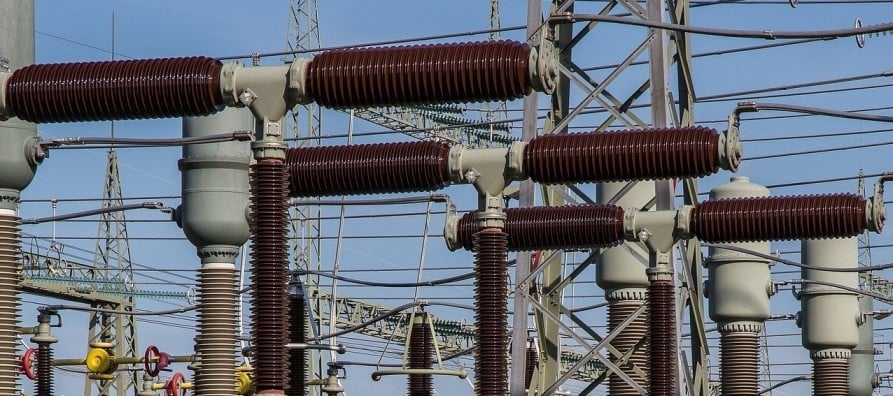
A substation is one of the most consequential pieces of infrastructure in a power grid. It steps voltage up or down, routes power between circuits, protects the network from faults, and connects generation to consumers. When it works, nobody notices. When it fails, entire regions go dark.
Inspecting a substation is not like inspecting a building. The equipment is energized, often operating at tens or hundreds of kilovolts, and the clearance distances that keep inspection staff safe are measured in precise fractions of a metre. Sending a team into a live yard with tape measures, clipboards, and ladders introduces genuine risk while producing measurement data that is frequently incomplete, inconsistently recorded, and impossible to reuse.
3D laser scanning changes that equation. It produces a complete, millimeter-accurate digital record of the entire substation, typically in a single site visit, with field personnel working at safe distances from live equipment. The result is not just a better inspection record; it is a foundation for every capital planning, compliance, and maintenance decision the asset owner will make over the next decade.
A substation scan captures everything visible in the yard in one visit. No return trips to remeasure a forgotten dimension. No arguments about which version of the drawing is current.
What a Substation Actually Contains
Before explaining what scanning captures, it helps to understand what is actually in a substation yard. Teams encountering a substation for the first time frequently underestimate its complexity.
Primary Equipment
• Power transformers: large oil-filled units that step voltage between transmission and distribution levels. They sit on concrete pads, connect to overhead bus work, and are surrounded by oil containment bunds.
• Circuit breakers: interrupt fault currents. They may be air-blast, oil, SF6, or vacuum type depending on age and voltage class.
• Disconnect switches (isolators): manually or motor-operated switches that isolate sections of the yard for safe maintenance.
• Current and voltage transformers: instrument transformers that feed metering and protection relays.
• Surge arresters: protect equipment from lightning and switching transients.
Support structures and civil works
• Steel lattice or tubular bus support structures carrying the overhead conductors between equipment bays.
• Rigid or strain bus conductors connecting equipment at precise heights and clearances.
• Cable trenches and conduit systems routing control and protection cables below grade.
• Concrete equipment pads, oil bunds, perimeter fencing, access roads, and drainage.
• Control building and relay room, often a separate structure within the fenced yard.
Every one of these elements has dimensional relationships to every other element. Clearances between live conductors and grounded structures are regulated. Equipment replacement requires knowing the exact footprint of what is being removed and the space available around it. None of that information can be reliably extracted from drawings that may be 20 or 40 years old.
Why drawings fail: Most substations were built in stages over decades. Each addition was documented separately. The resulting drawing set is a patchwork that no single person fully understands and that has never been reconciled against what is physically on site.
The Scanning Process in a Live Substation
Scanning a substation differs from scanning a building or industrial plant in one important respect: the environment is energised, and the proximity rules that govern how close any person or equipment can get to live conductors are non-negotiable. A competent scanning team plans the survey around those constraints, not around the convenience of scanner placement.
Pre-survey planning
Before any equipment arrives on site, the scanning team works with the asset owner’s safety team to establish:
• Which parts of the yard are live and which are isolated or de-energised
• Minimum approach distances for the voltage classes present
• Whether a safety observer or authorised person is required at each scanner location
• The sequence of scanner positions that achieves full coverage while keeping personnel safe
This planning phase is where substation scanning differs most from general industrial scanning. A team that treats a substation like a warehouse will either produce incomplete data because they could not get close enough, or create a safety incident because they did not understand what they were standing next to.
Site capture
The scanner is set up at a series of positions throughout the yard, typically on a tripod at ground level or on an elevated platform where greater vertical coverage is needed. At each position, the scanner rotates through a full 360-degree sphere, emitting millions of laser pulses and measuring the return time of each one.
A mid-size substation, perhaps 10 to 15 bays covering a two-hectare yard, can usually be captured in a single day. Larger transmission substations may require two days. The scanner operator moves the instrument between positions while remaining at the safe distances established in the pre-survey plan.
Reflective registration targets, small spheres or flat checkerboard panels, are placed at positions visible from multiple scanner setups. These shared reference points are what allow the individual scans to be mathematically combined into a single unified point cloud.
Post-processing and deliverables
The raw scan data is processed back in the office. Registration software aligns all individual scans into a single coordinate system. The resulting point cloud is cleaned to remove noise and duplicate data, then delivered to the client or used as the basis for further modelling work.
Typical deliverables include:
• Registered point cloud in RCP, E57, or RCS format — navigable in standard review software
• Dimensioned plan views, sections, and elevations in DWG or PDF format
• 3D CAD or BIM model of the substation at the agreed level of detail
• Clearance verification reports where NERC or IEEE compliance checking is required
• Asset inventory extracted from the scan data with equipment positions and dimensions
What Substation Scanning Is Used For
The value of a scan survey compounds over time. The initial scan delivers immediate insight for the project that commissioned it, but the point cloud and BIM model continue to pay back across a range of subsequent uses.
| Use case | What scanning captures | Operational benefit |
| Equipment condition assessment | Transformer geometry, bushing positions, oil-filled tank profiles | Early identification of deformation, settlement, or corrosion |
| Clearance verification | Precise gap between live conductors, structures, and access routes | Confirms compliance with NERC and IEEE clearance standards |
| Capital upgrade planning | Full yard geometry for new transformer, switchgear, or protection relay bay | Design and clash-check new equipment installation before procurement |
| As-built documentation | Complete 3D record of bus work, cable routes, conduit, and structural steelwork | Replaces or supplements outdated paper drawings |
| Post-event inspection | Rapid site capture after fault, fire, or storm damage | Supports insurance claims, forensic analysis, and restoration planning |
| Digital twin creation | Full-site BIM model updated over successive scan campaigns | Continuous asset record for operations, maintenance, and planning |
Transformer replacement planning
Replacing a large power transformer is one of the most expensive and logistically complex operations in substation asset management. A new unit must fit the existing pad, clear all surrounding structures at the required distances, and connect to the existing bus work without requiring wholesale reconstruction of the bay.
Doing this design work from outdated drawings risks arriving on site with equipment that does not fit. Doing it from a point cloud gives the engineer exact knowledge of available clearances, pad dimensions, cable entry positions, and overhead obstruction heights. The transformer can be modeled and clash-checked in the digital environment before procurement. That alone can save several weeks and significant cost.
Clearance compliance verification
Electrical clearances between live conductors and grounded structures, and between conductors of different phases, are mandated by NERC FAC standards in North America and equivalent regulations in other jurisdictions. These clearances are not static: structures settle, conductors sag as they age and as loading changes, and modifications to one part of the yard can inadvertently reduce clearance elsewhere.
A scan survey captures the actual as-built clearances across the entire yard. Automated clearance analysis tools can then flag any location where a measured gap is below the minimum required. This gives the asset owner a defensible compliance record and an early warning of developing problems.
Post-event damage assessment
When a substation suffers a fault event, fire, or weather damage, one of the first tasks is to understand exactly what has changed. How far has the transformer shifted? Which bus structures are still plumb? What is the extent of conductor damage? Getting people into a damaged yard quickly and comprehensively is both difficult and risky.
A scan survey provides a complete before-and-after record. If a pre-event scan is available, the comparison is straightforward: overlay the two point clouds and every deviation is immediately visible. Even without a pre-event scan, a post-event survey provides the detailed geometry that restoration engineers, insurers, and investigators need.
Digital twin development
Utilities increasingly manage their transmission and distribution assets through digital twin platforms: continuously updated virtual models of the physical infrastructure. A substation scan provides the geometric foundation of that twin, with equipment positions, dimensions, and spatial relationships that no other method can produce at comparable accuracy and completeness.
The scan is not a one-time exercise in this context. Periodic rescans, perhaps every five years or following significant modifications, keep the digital twin current. The accumulated scan history becomes a longitudinal record of how the substation has changed over time, valuable for both engineering and regulatory purposes.
Safety Is the Decisive Argument
Everything else, the accuracy, the speed, the reusable deliverable, is a bonus. The fundamental reason scanning belongs in substation inspection is that it keeps people away from live high-voltage equipment.
Traditional survey methods require personnel to work within the substation yard, sometimes at height, sometimes adjacent to energised equipment, measuring dimensions that a scanner can capture from a safe distance in a fraction of the time. Every additional hour a person spends in a live substation yard is an additional hour of exposure to a working environment where a single error in judgement can be fatal.
Specific safety advantages
• The scanner captures conductor heights, bus sag, and equipment clearances without any person approaching the energised equipment.
• Areas that are inaccessible or too hazardous for manual measurement, particularly near energised bus work at height, are captured from safe scanner positions at ground level.
• Fewer personnel on site for less time reduces the statistical exposure to electrical hazards, slip/trip risks, and the unpredictable nature of operating substations.
Post-event surveys after faults or storms can be completed before the yard is fully made safe for hands-on work, providing engineers with geometry data earlier in the restoration process.
Industry context: Arc flash and electrocution remain leading causes of serious injury in electrical utility work. Any method that reduces the time field staff spend near energised equipment directly reduces the probability of a life-changing or fatal incident.
What to Look for When Commissioning a Substation Scan
Not every scanning provider is equipped to work in a substation environment. The combination of high-voltage safety requirements and the precision needed to produce useful deliverables narrows the field considerably. A few questions help identify providers who will deliver the right result.
Electrical safety competence
Ask specifically whether the scanning team holds or works under relevant electrical safety qualifications for the voltage class present at your facility. In the U.S., this typically means OSHA 29 CFR 1910.269 training for high-voltage work. In practice, this usually means the scanning team works under the supervision of an authorised person from the asset owner’s organisation, but the scanning team must understand the safety context they are operating in.
Substation-specific experience
General building or industrial scanning experience does not automatically transfer to substations. Ask for examples of substation projects completed: the voltage class, the size of the facility, and the deliverables produced. A provider with a history of power-sector work will understand clearance requirements, will know how to plan scanner positions around live equipment, and will produce deliverables that utility engineers can actually use.
Deliverable specification
Be explicit about what you need. A point cloud alone is useful as a reference but requires the receiver to have specialist software. A dimensioned set of drawings serves most planning and maintenance purposes. A full BIM model is the highest-value deliverable but costs more and takes longer to produce.
Be explicit about what you need. A point cloud alone is useful as a reference but requires the receiver to have specialist software. A dimensioned set of drawings serves most planning and maintenance purposes. A full BIM model is the highest-value deliverable but costs more and takes longer to produce.
Accuracy specification and validation
Ask for the registered accuracy of the point cloud, meaning how well individual scans are aligned relative to each other. For substation work, registered accuracy of 3 to 5 millimetres is typical and sufficient for most applications. If clearance compliance reporting is required, confirm the accuracy is sufficient to support the specific standard being checked.
Coordination with your operations team
The best scanning providers will want to be involved in the access and safety planning process, not just arrive on the day. If a provider does not ask detailed questions about the energisation status of the yard, the voltage classes present, and the access and safety arrangements, that is a significant warning sign.
Where Substation Scanning Is Heading
The technology and the workflows are still developing. Several trends are worth noting for asset owners thinking about how scanning fits into their longer-term asset management strategy.
Mobile and drone scanning
Handheld and vehicle-mounted LiDAR systems are becoming accurate enough for substation survey work. These systems can cover large yards faster than tripod-based scanners, at the cost of slightly lower spatial density. Drone-mounted LiDAR adds the ability to capture conductor geometry from above, including sag measurements over the full span of each conductor run, without requiring elevated platforms or personnel at height.
AI-assisted point cloud analysis
Manually identifying equipment types, extracting clearance measurements, and detecting deformation in point cloud data is time-consuming. AI tools trained on substation imagery are starting to automate parts of this work: recognising transformer types, automatically measuring phase-to-phase clearances, flagging structures that appear to have moved since a previous scan. These capabilities will reduce the cost of extracting value from scan data and make regular scan campaigns more economically viable.
Integration with asset management systems
The long-term goal for most utilities is a seamlessly connected asset management ecosystem: work orders, maintenance records, inspection findings, and geometric data all linked to the same digital representation of the physical asset. Substation point cloud data and BIM models are increasingly being integrated with ESRI GIS platforms, SAP asset management systems, and utility-specific operational technology, creating a single source of truth for each facility.
Scanning as a standard pre-outage deliverable
Perhaps the most significant near-term shift is the growing expectation that a scan survey is part of the standard pre-outage preparation package for any major substation project. Just as a geotechnical investigation is now expected before a transmission tower foundation is designed, a scan survey is increasingly expected before any significant substation modification begins. The cost is modest relative to project value; the risk reduction is substantial.
The Case in Summary
Substations are ageing. The majority of North America’s high-voltage substation infrastructure was built between 1950 and 1990, and a large proportion of it is approaching or past its original design life. The capital expenditure required to refurbish, upgrade, and in many cases replace this infrastructure over the next two decades is enormous.
Every dollar of that capital spends better when the engineering work that guides it is based on accurate information about what is actually on site. 3D laser scanning provides that information, faster and more completely than any alternative method, with less risk to the people involved.
The technology is proven, the workflows are mature, and the safety case is clear. For any utility or asset owner planning substation inspection, capital upgrade planning, compliance documentation, or digital twin development, laser scanning is not an experimental option. It is the right tool for the job.